Understanding Ansys Mesh Settings – FEA Tips |
您所在的位置:网站首页 › ansys relevance › Understanding Ansys Mesh Settings – FEA Tips |
Understanding Ansys Mesh Settings – FEA Tips
|
5 (4) Introduction Meshing a part for analysis purposes is both a technical skill and an art. Every engineering analyst should strive to create an efficient mesh for their simulations. An efficient mesh is one which provides a desirable balance between accuracy and computational cost (mesh generation and solution run time). An analyst must try to achieve the the right balance which can be a daunting task at times. Fortunately, meshing software provide a variety of tools and features which can enable the analyst to generate high quality meshes. In this article we will discuss some of the features which are available in Ansys Mechanical. Preparing the GeometryPreparing a geometry for meshing purposes is one of the most important (and often overlooked) phases of an engineering simulation project. No amount of meshing features can compensate for a “dirty” geometry. Needless to say, it is best to detect and repair any geometric defects which may exist in the geometry prior to working on mesh generation. You can read more about geometry repair in this article on repairing geometry using design modeler. Ansys Mesh SettingsIf you click on Mesh in the Project tree within Ansys Mechanical, you will see a number of settings under “Details of Mesh”. We will discuss each of these settings individually. The content that follows has been derived from Ansys help documentation. 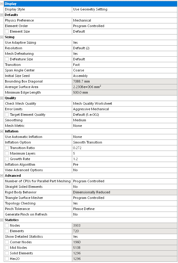 Mesh Details Defaults: Display Style Mesh Details Defaults: Display Style This enables you to change the display of the mesh in the graphical display window based on different criteria. The options are based on various mesh metrics. You can read more on Ansys mesh metrics in this article – Ansys Mesh Metrics Explained. Physics PreferenceThis option allows you to specify how Workbench will perform meshing based on the physics of the analysis type that you specify. The meshing options and the default for various meshing controls are dependent on the physics type. For this article we will assume that the Physics Preference is set to “Mechanical”. Element OrderThe global Element Order option allows you to control whether meshes are to be created with midside nodes (quadratic elements) or without midside nodes (linear elements). Reducing the number of midside nodes reduces the number of degrees of freedom. Examples are presented below. The heavy vertical line in each graphic represents the body boundary. Program ControlledFor surface bodies and beam models, Program Controlled is identical to the Linear option described below. For solid bodies and 2-D models, Program Controlled is identical to the Quadratic option described below. LinearThe Linear option removes midside nodes on all elements. Examples shown below are for a solid body. 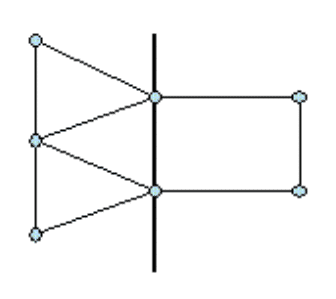 Linear Element [1] Quadratic Linear Element [1] Quadratic The Quadratic option retains midside nodes on elements created in the part or body. All elements will have midside nodes. 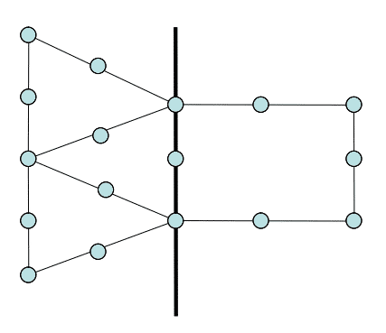 Quadratic Element [1] Quadratic Element [1] You can read more about element order in these articles : Linear vs Quadratic FE Elements Solid vs Shell vs Solid Shell Elements Element SizeThis is exactly as the name specifies – It is the size of a mesh element. This settings allows you to specify the element size used for the entire model. This size will be used for all edge, face, and body meshing. For solid elements the size of the element is defined based on the length of a diagonal. For surface elements, the average surface area and a factor. Sizing: Adaptive SizingAdaptive Sizing is an approach that refines edges in a 2D space based on curvature and proximity without extending the refined mesh across the face. It utilizes parameters like Resolution, Span Angle Center, and Transition. Historically it has been used to minimize element count while capturing every edge in the model. However, this method can excessively stretch the mesh, leading to poor mesh quality. As an alternative, it is recommended to use other sizing options and and techniques such as mesh based defeaturing to optimize element count. When ‘Use Adaptive Sizing’ is enabled, the mesher takes the ‘element size’ property as the initial mesh size reference. This property can either be user-defined or automatically computed through Defaults. Initially, edges are meshed using this size, then refined considering curvature and 2D proximity. Following this, mesh-based defeaturing and pinch control processes take place. Finally, the resultant edge mesh undergoes a least-squares fit size function, guiding the meshing of faces and volumes. ResolutionThe Resolution option controls the mesh distribution. The range of values that can be set is 0 to 7, with the mesh resolution changing from coarse (0) to fine (7). Mesh DefeaturingWhen Mesh Defeaturing is Yes (default), features smaller than or equal to the value of Defeature Size are removed automatically. This can be especially useful when you want the mesher to ignore geometric features such as close vertices, chamfers, radii, fillets and holes. TransitionTransition affects the rate at which adjacent elements will grow. Slow produces smooth transitions while Fast results in more abrupt transitions. Span Angle CenterThis feature sets the goal for curvature-based refinement. For a curved region, the mesh will subdivide along the curvature until the individual elements span this angle. You can set the span angle by choosing one of the following options: Coarse – 91o to 60o Medium – 75o to 24o Fine – 36o to 12o See also What is a Shape Function?Initial Size SeedThis setting allows you to control the initial seeding of the mesh size for each part. Assembly (default) bases the initial seeding on the diagonal of the bounding box that encloses all assembly parts regardless of the number of suppressed parts. As a result, the mesh never changes due to part suppression. Part bases the initial seeding on the diagonal of the bounding box that encloses each particular individual part as it is meshed. The mesh never changes due to part suppression. This option typically leads to a finer mesh and is recommended for situations where the fineness of an individual part mesh is important relative to the overall size of the part in the assembly. Quality: Check Mesh QualityThis setting establishes how the mesher treats error and warning limits: Yes, Errors (default) – If a mesh cannot be generated that passes all error limits, an error message is printed and meshing fails. Yes, Errors and Warnings – If a mesh that passes all error limits cannot be developed, an error message is printed and meshing fails. In addition, if a mesh that passes all warning (target) limits cannot be created, a warning message is printed. No – This option turns off most quality checks, but some minimal checking is still performed. In addition, even with the No setting, the target quality metrics are used to improve the mesh. The No setting is intended for troubleshooting and should be used with caution as it could lead to solver failures or incorrect solution results. Mesh Quality WorksheetThe Mesh Quality Worksheet helps you in measuring the quality of mesh and improving the mesh by provide visualization tools for identifying regions with low quality mesh and . The Mesh Quality Worksheet displays the quality criteria based on the Physics Preference. When you change the Physics Preference, the worksheet metrics column is reset to the default values. Error LimitsError limits are determined by the physics preference . You cannot change the error limits. You can think of the error limits as the minimum quality criteria of the meshing. Standard Mechanical – These error limits have proven to be effective for linear, modal, stress, and thermal problems. Aggressive Mechanical – These error limits are more restrictive than the error limits for Standard Mechanical. Aggressive Mechanical may produce more elements, fail more often, and take longer to mesh. As an alternative, you can set Physics Preference to Nonlinear Mechanical. However, doing so changes other defaults and may significantly change the mesh size and/or which features the mesh is capturing, and therefore may have a big impact on mesh quality. Nonlinear Mechanical – Uses error limits to produce a high quality mesh that meets the shape checking requirements of tetrahedral elements for nonlinear analysis. If the element quality cannot meet the error limits, the mesh is not desirable for nonlinear analysis. Target Element QualityYou can read on Element Quality in this article : Ansys Mesh Metrics Explained This option allows you to set a target Element Quality that you would like the mesh to satisfy. The Target Element Quality value drives improvements to tetrahedral elements. If you set the target quality and the mesh contains tetrahedral elements, the mesher will attempt to improve the tetrahedral elements to meet the target quality that you specified. If the target quality cannot be met, a valid mesh may still be generated. You should set the target quality if you intend to run a simulation that is sensitive to mesh quality. However, because setting the target quality increases memory usage and the time required to generate the mesh, you should not set the quality any higher than necessary. To set the Target Element Quality, enter a value between 0 (lower quality) and 1 (higher quality). The default is 0.05. SmoothingSmoothing attempts to improve element quality by moving locations of nodes with respect to surrounding nodes and elements. The Low, Medium, or High option controls the number of smoothing iterations along with the threshold metric where the mesher will start smoothing. Mesh MetricThe Mesh Metric option allows you to view mesh metric information and thereby evaluate the mesh quality. Inflation:Inflation refers to a thin layer of fine mesh (relative to the rest of the mesh) which is typically used to model physical phenomena exhibiting sharp gradients. A fine mesh is usually required to accurately capture such gradients. Inflation is useful for CFD boundary layer resolution (capture velocity, temperature etc.) electromagnetic air gap resolution or resolving high stress concentrations for structures. We will not go over the details of inflation in this article. Ansys help documentation contains thorough detail on this subject. Advanced: Number of CPUs for Parallel Part MeshingSets the number of processors to be used for parallel part meshing. Using the default for specifying multiple processors will enhance meshing performance on geometries with multiple parts. The default option instructs the mesher to use all available CPU cores. The Default setting inherently limits 2 GB memory per CPU core. An explicit value can be specified between 0 and 256, where 0 is the default. Straight Sided ElementsThe Straight Sided Elements option allows the mesher to generated elements with straight sides (as opposed to curved). See also ANSYS Mesh Methods ExplainedThis option may affect the placement of midside nodes if the Element Order option is set to Quadratic and is not available if the Element Order option is set to Linear. Straight sided elements are of relatively low quality and are generally not preferred. They are not able to capture curvature as well as Quadratic elements without straight sided elements.  Straight Sided Elements: Yes vs No [1] Rigid Body Meshing Straight Sided Elements: Yes vs No [1] Rigid Body Meshing The Rigid Body Behavior option determines whether a full mesh is generated for a rigid body, rather than a surface contact mesh. Rigid body meshing simplifies the representation of a model by reducing it to the contact regions and the centroid of the model. That is, when a part is defined as a rigid body, the mesher knows to mesh only the contact regions, and to create a single mass element at the centroid of the model. Triangle Surface MesherThis option determines which meshing algorithm will be used for patch conforming meshes. In general, the advancing front algorithm provides a smoother size variation and better results for skewness and orthogonal quality. Topology CheckingThe Topology Checking option controls what happens when a user scopes an object (such as loads, boundary conditions, Named selections and so on) to geometry (bodies, faces, edges, and vertices) after the mesh has been generated. If Topology Checking is set to Yes (default), the software will check to see if the scoped geometry has mesh properly associated to it. If the associations are incorrect, the scoping of the object will force the mesh to be out of date. The mesh would need to be re-generated to get proper associations. If the associations are correct, the scoping is performed without any change to the mesh and the mesh stays up to date. Set Topology Checking to No to avoid the checks and always keep the mesh up to date. Topology Checking is defaulted to Yes as it is important to have proper associations between geometry and mesh in order to properly transfer the loads to the solver. The best practice is to define all loads and boundary conditions prior to meshing so that the topology is properly captured during meshing. Pinch ToleranceThe Pinch feature lets you remove small features (such as short edges and narrow regions) at the mesh level in order to generate better quality elements around those features. The Pinch feature provides an alternative to Virtual Topology, which works at the geometry level. The two features work in conjunction with one another to simplify meshing constraints due to small features in a model that would otherwise make it difficult to obtain a satisfactory mesh. When Pinch controls are defined, the small features in the model that meet the criteria established by the controls will be “pinched out,” thereby removing the features from the mesh. The Pinch Tolerance control allows you to specify a tolerance for the Meshing application to use when it generates automatic pinch controls. Vertex-vertex pinch controls will be created on any edge with a length less than the specified tolerance, and edge-edge pinch controls will be created on any face for which two edges are within proximity according to the specified tolerance. The value that you specify for Pinch Tolerance should be smaller than the mesh size around the region in which the pinch control is being applied. For example, if an Edge Sizing control has been placed on an edge, a Pinch Tolerance value that is greater than that edge sizing may cause the mesher to fail. In general, the value that you specify for Pinch Tolerance should be greater than the value that appears in the Sizing > Minimum Edge Length field. Exceptions to this guideline include models without seam edges, such as elliptical prism, cylinder, and sphere models. Do not specify an overly high value for the Pinch Tolerance control. The Pinch feature allows the mesher to mesh over geometry features as if they were not there, and a tolerance that is set too high can cause inverted elements. When Capture Curvature and/or Capture Proximity is set to Yes, the default pinch tolerance is 90% of the value of Curvature Min Size / Proximity Min Size (whichever is smaller). This differs from the tolerance used by the default mesh based defeaturing. Generate Pinch on RefreshThe Generate Pinch on Refresh control determines whether pinch controls will be regenerated following a change made to the geometry (such as a change made via a Design Modeler application operation such as a merge, connect, etc.). If Generate Pinch on Refresh is set to Yes and you change the geometry, all pinch controls that were created automatically will be deleted and recreated based on the new geometry. If Generate Pinch on Refresh is set to No and you update the geometry, all pinch controls related to the changed part will appear in the Tree Outline but will be flagged as undefined. References[1] Ansys Help Documentation – Global Mesh Controls How useful was this post? Click on a star to rate it! Average rating 5 / 5. Vote count: 4 No votes so far! Be the first to rate this post. We are sorry that this post was not useful for you! Let us improve this post! Tell us how we can improve this post? Post Views: 4,268 |
【本文地址】